


Compact Electromagnetic Flowmeter
Model: HMPCL-E10
Applications & Industries
Process control in industries such as water supply, heating,environmental protection, food processing, water conservancy, metallurgy, and pharmaceuticals
Product Overview
HMPCL-E10 Series electromagnetic flowmeter is a fully intelligent flowmeter developed using advanced domestic and international technology. It features high measurement accuracy, high reliability, excellent stability, and long service life.
During the design, material selection, manufacturing process, production assembly, and factory testing, every aspect is strictly controlled. The product line utilizes calibration equipment compatible with various diameters, and every flowmeter undergoes actual flow calibration before leaving the factory. Specialized mass production software and hardware have been developed for electromagnetic flowmeters to ensure long-term high quality and performance. The product features a wide-temperature-range LCD display with a simple and intuitive interface, comprehensive and practical menu functions, and easy button operation for convenient on-site use.
Important Notes:
1. Do not misuse this document.
2. The information in this selection guide is for reference only. This document should not be used as a product installation guide.
3. Complete installation, operation, and maintenance information is provided in the product manual.
Features
• Measurement accuracy unaffected by fluid density, viscosity, temperature, pressure, etc.
• No flow-obstructing components inside the measuring tube, eliminating pressure loss and clogging
• Simple structure, easy installation, low requirement for straight pipe sections
• No mechanical moving parts, robust and vibration-resistant
• Multi-electrode structure ensures stable measurement and high accuracy
• EEPROM retains set parameters and accumulated flow value during power outage
• Converter uses low-power microcontroller for data processing, ensuring reliable performance, high accuracy, and low power consumption. LCD display shows accumulated flow, instantaneous flow, flow velocity, flow percentage, etc.
• Bidirectional measurement system capable of measuring forward and reverse flow
• Low-frequency rectangular wave excitation improves flow stability, reduces power loss, and provides excellent low-flow characteristics
Measurement Principle
The electromagnetic flowmeter operates based on Faraday’s law of electromagnetic induction. Two detection electrodes are installed on the wall of a non-magnetic measuring tube, perpendicular to both the tube axis and the magnetic field lines. When a conductive fluid flows along the tube axis, it cuts through the magnetic field lines, generating an induced electromotive force (EMF), which is detected by the two electrodes.
The magnitude of the induced EMF is given by:
![]()
Where:
• U: Induced electromotive force (EMF)
• K: Instrument constant
• B: Magnetic flux density
• D: Inner diameter of the measuring tube
• V: Average flow velocity across the tube cross-section
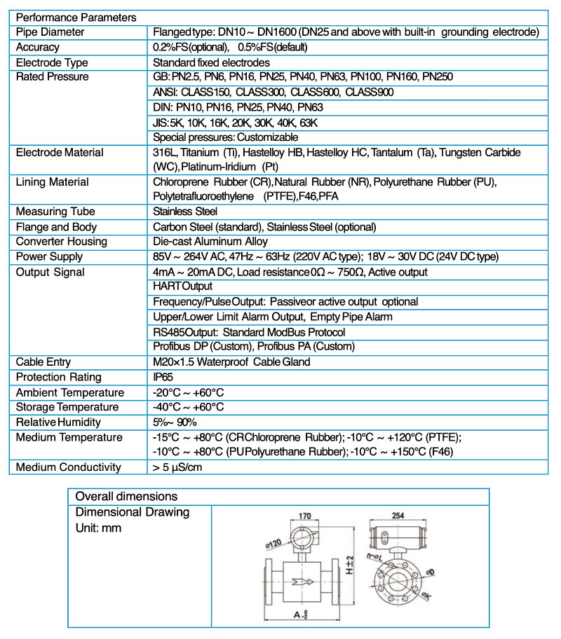
In the diagram above:
• A represents the length of the flowmeter guide tube;
• H represents the height of the flowmeter;
• n represents the number of bolt holes;
• L represents the diameter of the bolt holes;
• K represents the pitch circle diameter of the bolt holes;
• D represents the outer diameter of the flange.
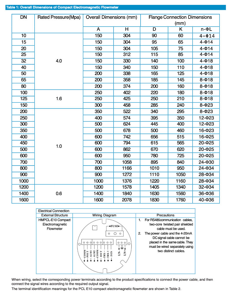
The overall dimension table for the compact electromagnetic flowmeter is shown below in Table 1.
Installation
1. Installation Precautions
(1) The electromagnetic flowmeter should be installed away from direct sunlight or locations with excessively high ambient temperatures to prevent the excitation coil from overheating, which could lead to insulation failure due to an unacceptable temperature rise.
(2) The flowmeter must be installed far from magnetic fields, such as those generated by large motors, large transformers, and welding machines.
(3) The flowmeter should be installed in a location free from vibration.
(4) The direction of fluid flow must match the direction indicated on the flowmeter’s label.
(5) The flowmeter is generally installed upstream of valves.
(6) The flowmeter must operate under full-pipe conditions; it cannot operate with an empty pipe or partially filled pipe. Ensure the measuring tube is always completely filled with the measured medium. Pay attention to the installation position, as shown in Figure 1.
Figure 1: Installation Position
2. Installation Orientation
During installation, the positive direction of fluid flow must align with the arrow direction indicated on the sensor. Adequate space for installation and maintenance must be reserved near the flowmeter.
Supports or pipe hangers should be installed on both sides of the flowmeter to prevent stress on the flowmeter caused by pipeline vibration, impact, or thermal contraction/expansion.
When installing an electromagnetic flowmeter, for horizontal installation, ensure the axis of the measuring electrodes is approximately horizontal. If the electrode axis is vertical, air bubbles may accumulate near the upper electrode, blocking fluid contact, while the lower electrode may become covered by sludge or impurities. The converter should generally be installed above the pipeline to prevent water ingress into the converter.
Figure 2: Installation Orientation
3. Flowmeter Piping Alignment
Misalignment between the pipeline axis and the flowmeter axis, or deviations between the pipeline flange and the flowmeter flange, are causes of flange runout and fracture. Therefore, during flowmeter installation, first correct any pipeline misalignment or inclination, as well as any deviations in the installation distance between the two flanges.
Figure 3: Flowmeter Piping Alignment
4. Required Straight Pipe Runs
To ensure the measurement accuracy of the electromagnetic flowmeter, straight pipe sections of a certain length must be maintained upstream and downstream of the flowmeter.
When valves are installed upstream or downstream of the flowmeter, the straight pipe runs must meet at least 5D upstream and 2D downstream (where D is the inner diameter of the flowmeter guide tube). Additionally, the upstream and downstream valves must be fully open during
Figure 4: Straight Pipe Runs with Upstream and Downstream Valves
When the electromagnetic flowmeter is installed downstream of a T-junction, a minimum straight pipe run of 5D must be maintained between the T-junction and the flowmeter, as shown in Figure 5.
Figure 5: Straight Pipe Run with a T-Junction Upstream of the Flowmeter
When the electromagnetic flowmeter is installed downstream of a 90° bend, a minimum straight pipe run of 5D must be maintained between the bend outlet and the flowmeter, as shown in Figure 6.
Figure 6: Straight Pipe Run Requirements After a 90° Bend
When the electromagnetic flowmeter is installed downstream of a valve that is not fully open, a minimum straight pipe run of 10D must be maintained between the valve outlet and the flowmeter, as shown in Figure 7.
Figure 7: Straight Pipe Run Requirements When Downstream of a Partially Open Valve
When the electromagnetic flowmeter is installed downstream of an expander, a minimum straight pipe run of 10D must be maintained between the expander outlet and the flowmeter, as shown in Figure 8.
Figure 8: Straight Pipe Run Requirements After an Expander
5. Converter Installation Grounding Requirements
The grounding terminal on the converter housing must be connected to earth ground using a copper grounding wire with a cross-section of no less than 1.6mm². The grounding resistance between the converter housing and the earth should be less than 10Ω.
Procedure:
1. Prepare a Φ20 mm copper tube, cut to a length of 1700 mm (can be extended if needed). Drive this copper rod into the ground to a depth of 1500 mm as an earth electrode.
Note: When driving the rod, sprinkle a layer of crushed charcoal at the tip and pour saltwater over it to improve conductivity.
2. Weld a 4 mm² copper wire to the top of the driven copper rod.
3. Finally, connect this grounding wire to the sensor flange, grounding rings (if used), and pipe flanges, as illustrated in Figure 9.
Important: The screws, spring washers, and flat washers used for securing the grounding wire must be made of stainless steel.
Figure 9: Converter Grounding Diagram

Selection Example:
HMPCL-E10-DN100 P16T0N5 E0EE1 C0F0G0 S0 B0A0 EX0
Model Description:
HMPCL-E10 Compact electromagnetic flowmeter, Pipe diameter of 100 mm, Rated pressure 1.6 MPa, Medium temperature 60°C, Lining material PTFE, Electrode material 316L, Built-in grounding electrode, Excitation coil housing material: Carbon steel, Connection flange material: Carbon steel, Power supply 24V DC, With 4~20 mA (with pulse/frequency) analog signal, With RS485 digital signal output, No matching accessories, No explosion protection requirements.
Model Selection Guide
According to statistics from world-renowned authorities, two-thirds of instrument failures in practical applications are caused by incorrect model selection and improper installation. Therefore, selecting the appropriate flowmeter is a critical task in practical applications. Please pay attention to the following during selection:
1. Collect Process Data
• a. Name of the fluid to be measured and the composition of any chemical substances it contains.
• b. Maximum flow rate, minimum flow rate, and normal flow rate of the fluid.
• c. Maximum operating pressure of the fluid.
• d. Maximum and minimum temperature of the fluid.
2. The fluid to be measured must have a certain level of conductivity, ≥ 5 μS/cm.
3. The maximum and minimum flow rates must conform to the values specified in the flow range table.
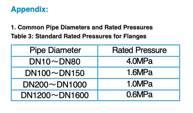
4. The actual maximum operating pressure must be less than the rated working pressure of the flowmeter tube.
5. The maximum and minimum operating temperatures of the fluid must comply with the temperature requirements specified for the flowmeter.
6. Determine whether there is a negative pressure condition existing in the process pipeline.
7. When measuring clean media, the economic flow velocity is 1.5 m/s to 3 m/s. When measuring easily crystallizing solutions, the flow velocity should be appropriately increased to 3 m/s to 4 m/s to achieve self-cleaning and prevent adhesion and sedimentation. When measuring abrasive fluids like slurry, the flow velocity should be appropriately reduced to 1 m/s to 2 m/s to minimize wear on the lining and electrodes. In practical applications, flow velocities rarely exceed 7 m/s, and velocities over 10 m/s are even rarer.
8. You can choose the appropriate electromagnetic flowmeter based on the actual situation. If the inner diameter of the selected flowmeter does not match the inner diameter of the on-site process pipeline, pipe reduction or expansion should be performed.
• a. If pipe reduction is carried out, consider whether the pressure loss caused by the reduction will affect the process flow.
• b. Considering measurement accuracy and product cost, a smaller diameter electromagnetic flowmeter can be selected to reduce economic investment.

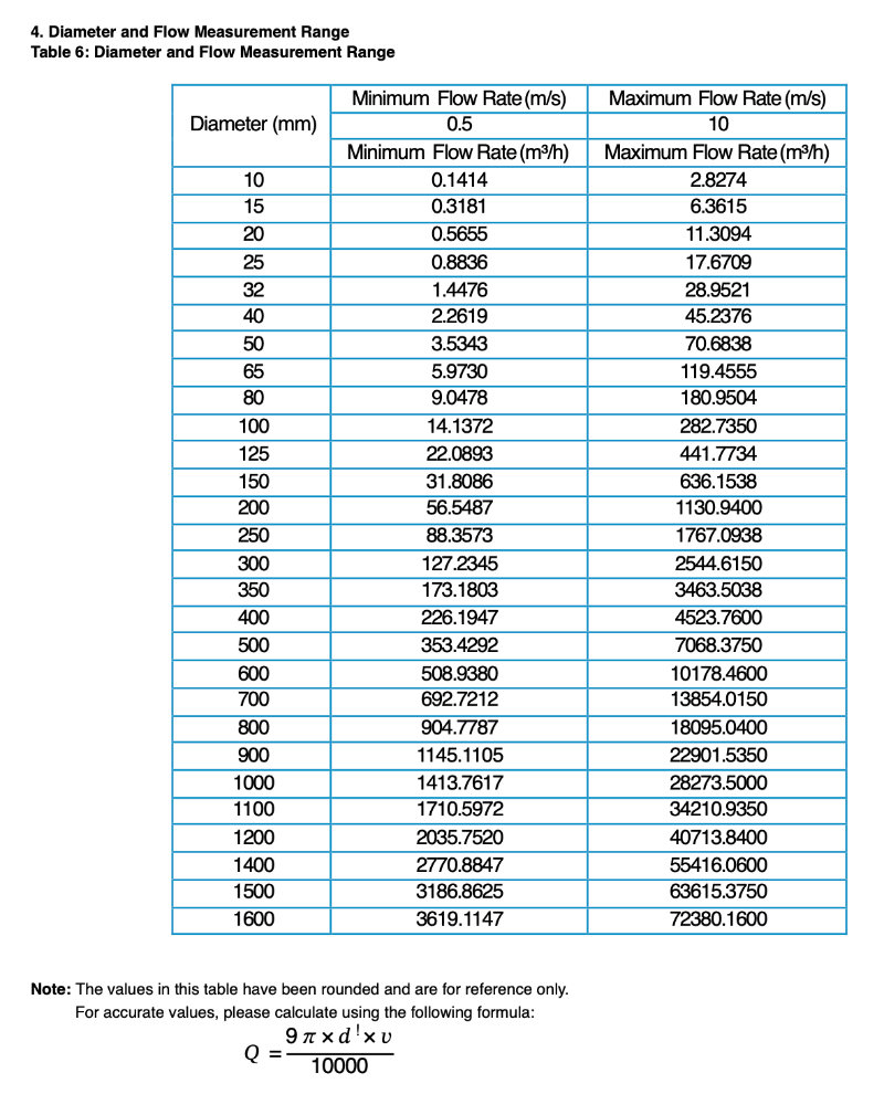
Where:
• Q: Flow rate (unit: m³/h)
• d: Flowmeter diameter (unit: mm)
• π: Pi, approximately 3.14
• v: Flow velocity (unit: m/s)
| Model | HM3051Y/C |
|---|


